The rotating vane anemometer is an instrument that is widely used in the field by maintenance engineers and inspectors. The anemometer consists of a vane that is held at right angles to an airflow. In modem instruments the speed of rotation of the vane is sensed and measured electronically and the air speed, which is a function of the speed of rotation of the vane, is indicated on a meter. The vane anemometer has a number of limitations: it is fragile and should not be used in corrosive or dusty atmospheres; it is not suitable for low velocities (below about 0.2 m/s); the vane tends to be large (usually about 100 mm in diameter) making it unsuitable because of access problems and blockage; it should be calibrated at frequent intervals. Because of the vane’s size and inertia, the anemometer integrates the air velocity spatially and temporarily which can be an advantage for some applications. It is a portable instrument and can measure over a wide range of velocities. The vane anemometer is often used to make measurements on fume cupboards, booths and at inlet and outlet grilles to measure velocities and calculate volume flow rates. However its use at grilles does present a problem. Because of the nature of the flow, especially at inlet grilles, the velocity indicated by the anemometer is not the true velocity. Air emerges from the grille in an array of jets and it is found that the effect of this is to make the instrument over-read.
In the case of thermal anemometers and swinging vane anemometers, the ACGIH manual of industrial ventilation gives correction factors to be applied at grille openings both under pressure and suction. However in the case of grilles under pressure (i.e. inlets) the range of applicability of the advice is very limited, particularly in relation to the open area i.e. 70% open area or greater. The free open area is used in calculations, with a velocity correction factor of 93%. Many grilles, especially at air inlets, but also on benches with perforated inlet and exhaust surfaces, can have open areas considerably less than 70%. In the case of rotating vane anemometers, no advice is given by ACGIH.
Experimental Method
A 100 mm diameter rotating vane anemometer which had been calibrated in-house was used for the investigation. The instrument was found to over-read by about 4%. Nine grilles with a range of geometries and open areas were chosen (see the Table). Six of the grilles had circular holes ranging from 1.2 to 8.0 mm in diameter which, depending on the pitch of the arrays, had open areas between 22 and 69%. The other 3 grilles had arrays of hexagonal, square and 204 rectangular holes, and open areas up to 79%. Additional measurements were made with the 1.5 mm diameter hole grille modified by blanking off alternate rows of holes to reduce the open area to 11 %. The grilles were mounted in turn across the end of a free standing 250 mm diameter duct through which the volume flow rate was measured using a flow grid. The flow rate was regulated to give mean duct velocities between 0.5 and 10 m/s.
| Hole geometry | Hole size: mm | Open area: % |
| Circular | 1.2 | 42 |
| Circular | 1.5 | 22 |
| Circular | 3.0 | 33 |
| Circular | 4.8 | 50 |
| Circular | 6.4 | 43 |
| Circular | 8.0 | 68 |
| Hexagonal | 6.0 | 79 |
| Square | 10.0 | 52 |
| Rectangular | 2.4 x 12.7 | 34 |
Measurements and Results
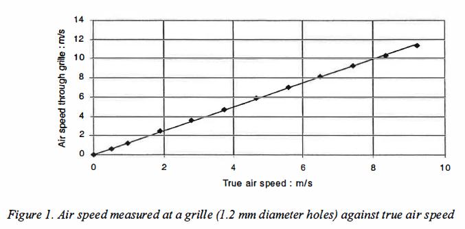
Velocities were measured at each grille with the vane anemometer resting against its surface. Figure I shows an example of the results for the 1.2 mm hole grille. In this case the measured speed was 25% higher than the true value over a range of speeds up to almost 10 m/s. This linear variation was found in all cases with an over-read as high as 41 % in the case of the modified array (11 % open area). Figure 2 shows the results for all of the grilles. It can be seen that as the open area decreases, the percentage error in the anemometer reading increases.
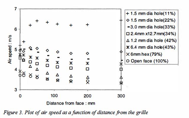
Measurements were also made of the variation of measured air speed with distance away from the grilles. Figure 3 shows this variation for a fixed volume flow rate. Comparison of the results for open areas of 33 and 34% shows that the shape of the 206 grille perforations has an effect on the air speed both at the grille and at distances away from it. Comparison of results for open areas of 42 and 43% shows that the hole diameters and/or the hole spacing has a significant effect on the variation of air speed with distance from the grille. Comparison of the data from the open ended duct and the 79% open area grille shows that there is very little difference in the two sets of results except very close to the grille.
Conclusions
• Vane anemometers used at inlet grilles with open areas less than 80% over-read. As the open area decreases, the percentage speed over-read increases.
• For grilles of equal open area and the same perforation shape, the size and/or spacing of the holes effects the variation of air speed with distance from the grille.
• The grille perforation hole shape affects the over-read.